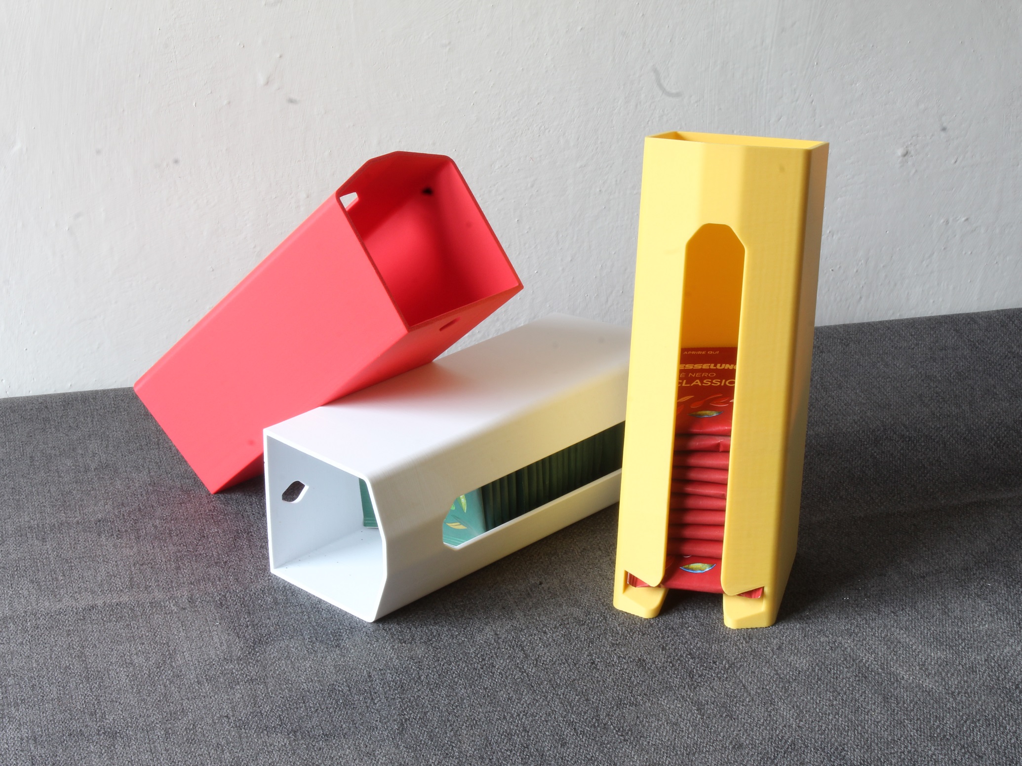
Designing 3D-Printed Prototypes That Survive the Jump to Injection Molding
The DFM checks that keep a validated print from becoming a redesign the moment it meets a steel tool.
The geometry that prints and tests perfectly is often the geometry that fails first-article inspection on the mold — not because the design was wrong, but because 3D printing let you skip constraints injection molding enforces the moment metal gets cut. Here's what to check before the tool is quoted.
Why Prototype Geometry and Production Geometry Diverge
An FDM or SLA/DLP printer builds a part layer by layer with no tool to eject it from. That single fact is the root of almost every DFM gap:
No draft is required
A vertical wall prints as a vertical wall. A molded part has to release from a steel cavity, so any wall parallel to the pull direction needs a taper or it drags and scars on ejection.
Wall thickness is nearly free to vary
A printer will happily lay down a 0.6 mm rib next to a 6 mm boss in the same part. Molten plastic flowing through that same transition in a mold pools, cools unevenly, and either sinks the opposite face or doesn't fill at all.
Sharp internal corners don't concentrate stress the same way
FDM parts fail along layer lines before a sharp corner becomes the weak point. Molded parts in the same geometry crack at that corner under far lower load, because injection-molded thermoplastic is far more sensitive to stress risers.
None of this shows up in a fit-and-function print review. It shows up three weeks later when the tooling quote comes back with a redesign line item, or worse, after the first-shot tool is already cut and the part won't release cleanly.
Draft Angles — Model Them In Before You Ever Cut a Tool
The standard rule of thumb toolmakers use is about 1° of draft per inch of cavity depth as a starting point, with 1–2° treated as the safe default for smooth vertical walls up to roughly 2 inches deep. Textured surfaces need more — as a rough guide, add roughly 1.5° of draft for every 0.001 inch of texture depth (SPI/PPS-style finishes), since texture increases the drag on ejection significantly. Deep ribs and thin-wall bosses often need 3–5° to release reliably. The mistake I see most often isn't ignorance of these numbers — it's applying them to the wrong surfaces at the wrong stage. If you add draft to every wall on your first prototype iteration, you've now changed the part's fit, its visual proportions, and possibly its function, before you've even confirmed the base geometry works. Two things fix this:
Draft only the faces that need it for production, and only after form/fit is locked
Mating surfaces, seal faces, and anything with a tight tolerance to another part usually stay draft-free or get draft added on the non-critical side only.
Model draft as a separate, suppressible feature
In Fusion 360 and SolidWorks, apply draft as its own feature in the timeline/tree, driven by a parameter (0° for the print-validation build, 1–3° for the tooling-ready build) rather than baking the taper into the base sketch. That way you print and test the 0° version now, flip one parameter later, and re-run interference checks without remodeling the part.
Wall Thickness — Where 3D Printing Lets You Cheat
Most FDM printers handle wall thicknesses from about 0.8 mm up to whatever fits your build volume without complaint. Resin printers go thinner still. Injection molding has a much narrower comfortable range — typically 1–4 mm depending on material and how far the melt has to flow before it freezes off. Go thinner and the shot doesn't fill; go thicker or uneven and you get sink marks, warping, and longer cycle times that make the part more expensive to produce than quoted.
The specific habit to watch for: ribs and bosses printed at full wall thickness because it was easy to model that way. In molding, ribs should run 50–60% of the nominal wall thickness they attach to, with a generous fillet at the base — full-thickness ribs almost always telegraph as a visible sink mark on the opposite face, and there's no fixing that after the tool is cut without adding cost for a texture or a design change.
Ribs, Bosses, and Fillets That Don't Survive the Transition
A few specifics worth checking on any prototype headed toward tooling:
Screw bosses
should keep wall thickness close to the nominal part wall, with an outer diameter roughly 2–2.5× the screw's major diameter, and a gusset or rib to the nearest wall rather than a boss floating unsupported.
Internal corners
need a fillet radius of at least 25–50% of the wall thickness. Sharp internal corners are the single most common source of unexpected mold-flow and stress-crack issues on parts that printed and tested fine.
Snap fits
that work as printed sometimes need a slightly different beam thickness or undercut angle once the material shifts from a printed polymer to the production resin, since stiffness and elongation-at-break aren't identical across materials even when they're nominally "the same" plastic family.
A Parametric Workflow: Print-Validate Now, Mold-Ready Later
The workflow that's saved the most redesign cycles on my projects is building the model as two named configurations from the same feature tree, not two separate files:
Print-validation configuration
draft suppressed or set to 0°, wall thicknesses as needed for the printed material's actual mechanical properties, no production-only features like ejector-pin flats.
Tooling-ready configuration
draft parameters activated, ribs re-checked against the 50–60% rule, fillets added at the internal corners, boss geometry reviewed.
Because both configurations pull from the same base sketches and reference geometry, changing something discovered during print testing — a wall that needs to move 2 mm, a boss that needs to relocate — updates both configurations at once instead of requiring you to re-sync two divergent models. It also means the DFM review happens as a design pass you can point to and justify, rather than a rushed edit against a tooling deadline.
This matters more once you factor in what a late catch actually costs. A single-cavity aluminum prototype tool typically runs $3,000–$8,000; a soft-steel bridge tool that can produce a few thousand parts before a production tool is cut runs $8,000–$20,000. A geometry problem caught in CAD review costs you an afternoon. The same problem caught at first-article inspection on a cut tool costs you a re-cut, and on a bridge tool that can mean the whole run slips by weeks.
When It's Fine to Skip Full DFM Prep
Not every printed part is headed for a mold, and it's worth saying plainly: if you're printing for a trade show model, an ergonomics check, or a one-off functional test that will never be reproduced at volume, adding draft and rib rules to the model is wasted effort. The trigger for doing this work is a real production decision — a customer commitment, a quote in hand, a bridge-tooling order placed — not "this might go to production someday." Doing DFM prep on speculative geometry just adds constraints to a design that's still supposed to be moving fast.
The judgment call is knowing which stage you're actually in, and being honest with a client or your own team about it before the CAD hours go in.
If you're validating a design as a 3D-printed prototype and know it needs to move toward injection-molded production, it's worth a CAD review before that transition rather than after. I work through this DFM pass as part of industrial design and CAD engineering projects that go from concept through 3D-printed prototyping to production-ready tooling — happy to look at a model and flag what needs to change before it goes out for a quote. More on the full process at makehasdai.com.
Need help with your 3D print?
The Makehasdai team prepares and prints your files — FDM, SLA and SLS. Shipping across Italy in 2–5 working days.